
In this session we’ll look at some ways to create and manipulate Civil 3D Sample Lines. On my screen I have a drawing that represents a road reconstruction project. Let’s zoom in, and we’ll do a quick tool. Right here, I have an alignment called Route 38B prop. This alignment was used to build this corridor called Route 38B. This corridor has a top surface defined called Route 38B top. I also have an existing ground service called EG.
I’m going to point where I’d like to place some sample lines such that I can pull some cross-sections. To create the sample lines, here on the home tab in the profile and section views panel, I’ll click the samples line button. I will then select my alignment, and then using the style log box on the left, I can name the sample Line Group. I can also choose my object and label style for the sample lines.
I’m going to keep the defaults in this case. Down below I can select the data in my drawing that I’d like to sample. Right here, you can see the existing ground surface. There’s the corridor, and there’s the top surface. I’d like to sample all of these. To the right, I can select a style for each. The style will come into play when I pull cross-sections in a little bit.
Let’s go with the sections plot style for my corridor, and then for the proposed surface, I’ll a proposed section style. And I’ll click okay. Next, I can determine where I’d like to place the sample lines along the alignment. We’ll use the menu in the tool bar for that. Notice that we have several options. From corridor stations, we’ll place a sample line at every assembly insertion along the corridor.
A more popular option is this one by range of stations. This allows us to place sample lines at designated increments along the alignment. I’m going to select that option. I can then use the style log box to adjust the settings. I do not want to place a sample line at the beginning of the alignment because the corridor doesn’t go that far.
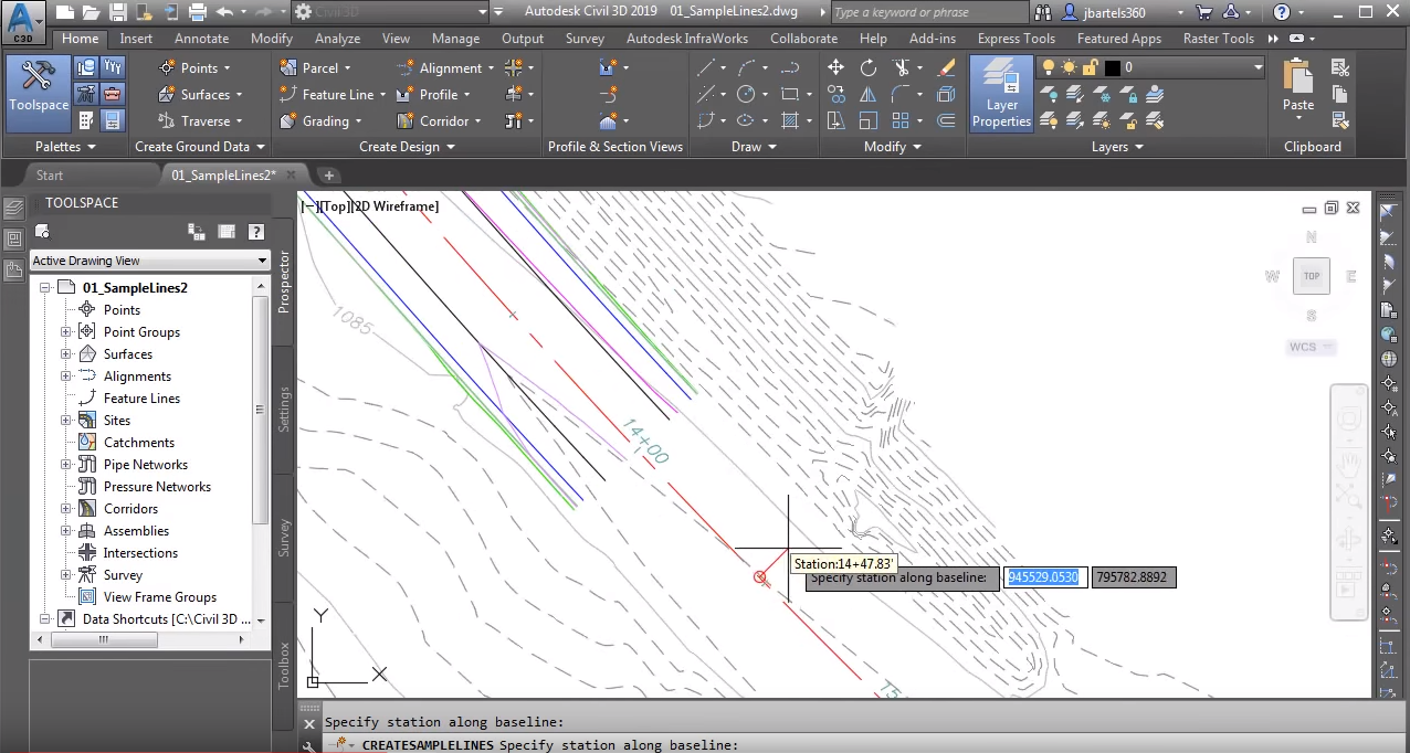
Instead, I’ll place my first sample line at Station 400, which will be right here. Likewise, I do not want to run the sample lines to the end of the alignment. I don’t know the station value for the ending, so I’m going to click this green block, and then I can pan the drawing up and find that location. Let’s go with Station 1450. Now, I could pick that point on screen, or I can just type 1450 and press enter.
If I drag this down, right here I can adjust the swath width on the left and right. Currently, these are set to 90 feet, so the resulting sample lines will be 180 feet long. Let’s stick with the defaults, and I’ll drag down. I’d like to place these sample lines using an increment. Let’s go with every hundred feet along the alignment. And I’d like to place a sample line at the range start and end. And I’ll click okay.
You can see some of the sample lines that have been created so far. Notice I am still in the command. That’s because it’s reverted to the “At a Station” method. This option allows me to place sample lines at the stations of my choosing. You might use this method to place sample lines at driveways, or the location of utilities as an example. We can add these manual sample lines by picking on screen.
I can then press enter twice to accept the left and right swath width. I could also change those measurements if I wanted to. Likewise, we could place manual stations by entering a station value. I’m going to type 975 in this case. I’ll press enter, and then I’ll press enter again to accept the swath widths. Let’s look at one more option.
I’m going to open the menu. Notice that we can also create sample lines by picking points on screen. Let’s pan the drawing over. I’m going to pick here, and here. As you can see, this option allows us to create non-perpendicular sample lines. Note, I could keep going if I wanted to. I’m going to press enter, and we’ll do one more. Maybe we’ll pick from here to here. I’ll press enter and then I’ll press enter again to exit the command.
If I back up, you can see the sample lines along my alignment. Let’s zoom in. If you select a sample line, you’ll see a series of grips. These grips are used to reposition or change the geometry of the sample lines. For example, if I click this diamond grip, I can use it to drag the sample line back and forth along the alignment. I can click to place it where I like, or if I select this again, you can see the station value right there at my cursor. We’re seeing that because my dynamic input is turned on.
If yours is not turned on, you could press F12 to toggle that. I’m going to place this back where it was. I’ll type 700 and I’ll press enter. If I select the square grip at the end, I can put a bend in the sample line. If click the triangular grip, I can extend or shorten the swath with the side. Likewise, if I select that triangular grip, I can adjust one of several dimensions.
Notice as I hit the tab key, I can cycle through these. This first measurement represents the distance this end point is from being perpendicular to the alignment. Currently, that’s 32. If I was to set to 20, you can see how that becomes closer to being perpendicular. Let’s click this grip again. I’ll press tab. This measurement shows us how far the grip is offset from the alignment.
Let’s press tab again. This measurement shows us the overall length of the segment. I’m going to type 90, and I’ll press enter. Now, once you’ve skewed a sample line, you may wonder how you can straighten it out. Well, knowing what we know now, I could click this triangular grip and set this first dimension to zero and I’ll press enter.
If I want it, could also restore the swath width by selecting the grip again. Press tab a couple a times to access the length measurement. I’ll type 90 and press enter. I’ll press escape when finished. Having seen that, let’s look at an even faster way to ensure sample lines are perpendicular to an alignment. I’ll select this sample line, for instance, and then I’ll simply right click and choose “Make or [Thoganole 00:05:25].”
I will then do a quick regen to clean up the screen. Now, after seeing this you may be wondering if it’s possible to create sample lines from your own geometry. We can certainly do that. I’m going to come up and launch the poly line command, and then I will create a segment through here and then maybe I’ll create one more right there.
To turn these into sample lines, we’ll come back and launch the sample line command. I’ll select the alignment. We are still in that same sample line group. Let’s open this menu again, and I’ll choose, “Select existing poly lines.” I’ll select both of these, and I’ll press enter a couple of times. You can see these are now sample lines. If I select the sample line, you can see the familiar grips.
I’ll use the diamond grip to drag the sample line along the alignment. Notice that the original poly line is retained. I’m going to get rid of this. I’ll select it and press delete, and we’ll pan this down. I will then select the sample line again, and we’ll adjust some of these other grips. Same as before, I can use the squares to move the end points, and then I can use the triangles to change the length of the segments.
Likewise, if I wanted to, I could right click on it and choose “Make or Thoganole.” Let’s do another quick regen and we’ll create some cross-sections. I’m going to pan the drawing over. I’d like to pull these sections at one inch equals 10 feet. So I’ll open up the scale menu and select that scale. To create the sections, I’ll come up to the profile in the section view’s panel and I’ll choose “Create multiple views,” and then by default my template is set appropriately to create production section views.
From here, I’ll choose “Create section views,” and then I’ll click on screen. If I zoom in, you can see that the views have been created and they’re arranged nicely so that they’ll fit on each sheet. The next time you’re placing sample lines, remember that they do not have to be perpendicular. By exploring some of the other creation tools and the grips, you can define sample lines with as many angles and bends as your design requires.


