
In this session we’ll look at how to assign widenings to civil 3D offset alignments. On my screen I have a sample alignment called Main Street. Let’s say that this alignment represents the center line of a proposed two lane road. Let’s also say that I would like to create some horizontal targets that I can use to drive the widths of the lanes. At this point, you’re probably aware if you were to launch the offset command and enter a lane width, you can select a civil 3D alignment and offset it to create a poly line.
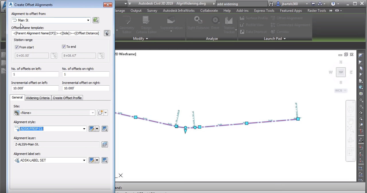
Now this poly line can certainly be used as a target. That being said, the poly line is static, so if your design were to change, you would have to update this offset geometry manually. Let me press escape, I’m going to delete the poly line, I’ll select that and press delete. Instead, I’m going to create my offset geometry using offset alignments. I’ll do that my selecting the parent alignment and then from the contextual ribbon I’ll choose offset alignment. I can then use this dialogue box to define my offsets. I’d like my offsets to be parallel to the main street alignment. I’d like the offsets to run from the start to the end of the station range. Note, I can use these toggles to assign a specific starting and ending station. Below I can select the number of offsets I’d like on the left and right side. I can create as many as I want and I can come back later and add more if necessary.
Since these offsets represent lane edges, I’m going to go with one to the left and right. I will then enter an offset distance of 12 feet for each. Using the general tab I can stylize these offset alignments since these represent the edge of pavement, I will choose the edge of pavement alignment style and I don’t need to see labels in this case. I’ll come down and click okay when finished. I’ll press escape and I’ll zoom in. As you can see I’ve created a pair of official civil 3D alignments. Note that the offset alignments can be found on the prospector tab within the alignments group within the offset alignments category. Since these are offset alignments they maintain a dynamic relationship to the parent alignment.
So if I change my design, you can see those offsets update automatically. Let’s press escape and we’ll zoom out. In addition to creating offsets I can also create widening to define geometry for turn lanes or on street parking. As an example, let’s widen this offset to create a right turn lane. I’ll do that by selecting the offset alignment and then from the contextual ribbon I’ll choose add widening. I can create this widening as it’s own alignment or I can add geometry to an existing alignment. I’m going to select that option. I can then choose where I’d like the widening to start, I can do that by picking a point on screen or I can enter a station. I’m going to type 500 in this case. And then where would I like the widening to end?
I’m going to snap to the end point of the alignment. Finally I can enter my widening offset, this distance is measured from the parent alignment. Since this offset represents two lanes, I’ll type 24 feet and press enter. This brings up a dialogue box containing parameters that I can use to update the widening geometry. I can adjust the offset, the start station, the region length. Notice that as I select these values the geometry is highlighted on screen. Moving back to the dialogue box I can control the transition. Currently this is set to linear, that said we do have some curve options as well. I can change the taper input type and I can change the transition length. As an example I’ll set this to 100 feet and I’ll press enter. You can see the change onscreen.
Let’s close this dialogue box and I’ll pan this over. The alignment is still selected. I can also edit the geometry using these grips. For example I’ll hover over the offset grip and I can see the current offset. If I select this grip I can change it. I’m going to make it 18 and I’ll press enter. You can see the change, I’ll click the grip again and I’ll set that back to 24 and I’ll press enter. Note that I have my dynamic input turned on, that is what’s allowing me to change those values onscreen. If your dynamic input is turned off you can toggle it on by pressing F12. I can use these diamond grips to adjust the beginning and ending station of the 100 foot transition. Clicking this circular grip will expose additional grips that can be used to adjust the transition length. Selecting these I can pick on screen or assign stations for the beginning and ending of the transition.
Likewise, if I press the tab key I can enter a new overall transition length. Let’s set this back to 75 and I’ll press enter. Using the add grip I can add a widening to a widening. Let’s widen this to a third lane. I’ll click the offset grip and I’ll change this to 36 and press enter. One more side note, if you were to adjust offsets to the left of the parent alignment, they would be negative values. Let’s click the transition grip and I will drag this over. I will then click the grip on the end and I’ll press tab and we will set this to a 75 foot transition. Finally, after making some changes using grips, if I’d like to return to the tabular editor, I can make sure the alignment is selected and from the contextual ribbon I’ll chose offset parameters to display the editor on screen.
Note that since I have multiple widenings we can see each widening show up as a group in this menu. There’s group two and here’s group one. To wrap things up we’ll make a change to this final transition. I will select that and I’ll make this 100 and I’ll press enter. I will then click the x to close the dialogue box and I will press escape to de-select the alignment. Now, even though I have multiple offsets and multiple widenings, all of this geometry is dynamic to the parent alignment. If that alignment changes, all of these other entities will update as well. So if your linear design can be represented using multiple parallel entities, consider using offset alignments and widenings for some of the geometry. Not only are these objects easier to create, their dynamic nature also allows for faster design changes.


