
Starting in Civil 3D 2019.2, we can easily display linear crossings in a profile view. Each crossing is represented using a marker and label style. In this session, we’ll look at some ways to create custom marker styles. As you can see, we’re picking up where we left off in the last session. In that session we talked about the Tartans Drive alignments and Profile View. I then used the new Show Crossings feature to display the crossing of the Willow Lane alignments and finished great profile. I also chose to display the crossing edge of pavement for this existing roadway. Now, if you have not already, I would recommend watching that previous session first before continuing on. I’ll leave a link to the recording in the description for this one.
If you remember, when I created these crossings I used my own custom markers and labels. Today, we’ll learn how I created the markers. Let’s start by displaying the crossings using the out of the box generic marker style. I’ll do that by selecting one of the markers and from the contextual ribbon I’ll choose Crossing Properties. Using this dialog box, I can control the markers and label styles assigned to all of the crossings in this profile view. Since we’re not going to be working with label styles in this session, I’m going to set all of these to none. I can use this handy Set All option to assign several at one time. When it comes to the marker styles, I’m going to select this generic style called Standard for each of them. Same as before. I’ll use the Set All option to make this a little faster. When I’m finished, I’ll click OK and OK. I’ll press Escape to deselect and if I back up and pan over, we can see that all of the crossings are displayed using the same marker style.
Let’s pan back and I’ll zoom in. To create a custom marker style, I’m going to jump to the Settings tab of the tool space. Marker styles can be found within the General category, inside Multipurpose Styles. From here I’ll expand Marker Styles. Right here, we can see the styles I used in the previous session. To create a new marker style, I will right click on the heading and choose New. I will then use these tabs to configure the marker style. The Information tab is where we give the style a name. I’m going to call this cross feature. I will then jump to the Marker tab. Here’s where we configure the appearance of the symbol. That symbol could be an AutoCAD Point. We could select one of these custom markers. Note, if you select a custom marker, you have the option of choosing a circle or square embellishment. If desired an AutoCAD Block can also be used as the marker.
For this example, I’m going to select an X with these circles surrounding it. In the lower left, we can assign a rotation angle to the marker. I’m going to keep the default for now. In the upper right, we can assign a height to the marker. Opening the Options menu, we’ll find several choices. For now, I’m going to select the default Use drawing scale. This means that if the Civil 3D drawing scale changes, this marker will resize itself appropriately, such that it always measures 1/10 of an inch on the plotted sheet.
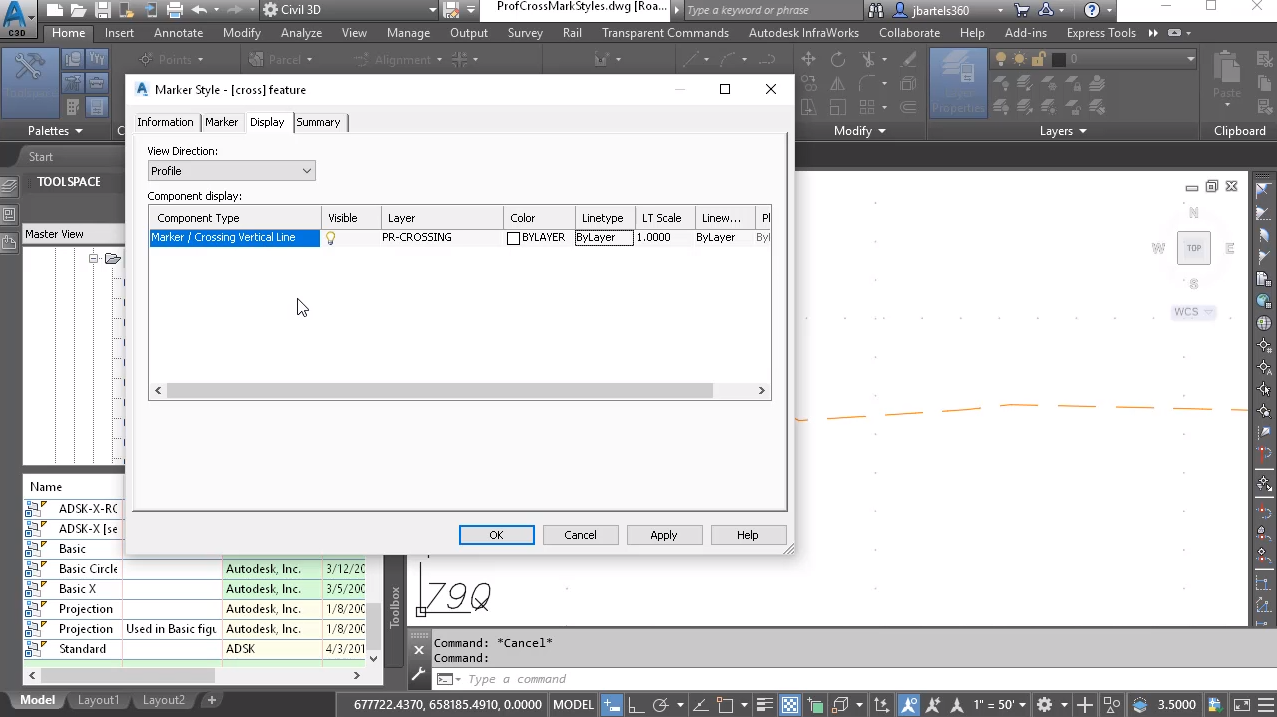
Next I’ll jump to the Display tab. Here’s where we control the general properties of the marker style. Things like layer, line type and color. Like all Civil 3D objects, styles, marker styles, are view dependent. So if I open the View Direction menu, you, I can say that when this marker style is viewed in a Profile view, I would like the marker to be visible. If I click here, I can select a layer. For this example, I’m going to come down and choose a layer called a PR-Crossing and I’ll click OK. I would like its color to be driven by the layer setting. We’ll do the same thing for the line type. I’ll keep the remaining default properties.
Just for a second, notice that the component references two items, Marker and Crossing Vertical Line. That’s because this marker style is dual purpose. If it’s assigned to a 3D linear item, like a profile feature line or survey figure, it will display as a marker. If it’s assigned to an alignment, it will display as a vertical line. By being dual purpose, you have the option of creating marker styles that apply to specific objects, or you can create one style that can be applied to multiple crossings. When finished configuring my marker style, I’ll come down and click OK. We can see that marker style now displays here in the list. To assign that style to this existing crossing, I’ll select the marker and choose Crossing Properties. Note that item is selected in the dialog box, so I’ll click the marker property and we’ll change this to Crossing Feature. I’ll click OK and OK, I’ll press Escape, and we can see the new marker style on screen.
Now, if I needed to make edits to this style, I could simply right click on the style name here in the tool space, and choose edit to bring back the settings. Let’s close this. Likewise, as a shortcut, I could select the marker itself, right click and choose Edit Crossing Style from the menu. Let’s close this. I’m going to pan the the drawing over. Next, we’ll create a marker style for the crossing profile. In this case, I’d like the marker to be very similar, so rather than reinventing the wheel, I’m simply going to right click on the previous style, and choose Copy. On the information tab, I’ll change the name to Cross Profile for the marker. I’m going to keep the exact same symbol in size.
Let’s go to Display. When this marker is displayed in a profile view, I’d like to keep the same layer. However, I would like the color of the marker to be blue. Let’s click OK and OK. To apply the new style to this marker, I’ll select it. We’ll go to Crossing Properties. I’ll click its marker property, and I’ll select the new marker style. I’ll click OK and OK, and I’ll press Escape. Finally, we’ll create a marker style for the alignment crossing. Same as before, I’m going to right click on a previous style and choose Copy. On the information tab, we’ll call this cross alignment. For the marker, I’m not going to adjust any of these settings. Since I’ll be assigning this to an alignment, the marker really won’t matter. It’s going to display as a vertical line.
Let’s jump to the Display tab, and I’ll switch the view to Profile. I would like that vertical line to be drawn on the PR-Centerine-Road layer. Let’s click OK. All of its other properties will be by layer. This is perfect. Let me click OK. I’ve just created another style. Let’s select this marker. We’ll go to Crossing Properties, and it will use the new alignment marker style. I’ll click OK and OK. I’ll press Escape, and we’ll back up a little and take a look.
As you can see, very quickly we can set up as many marker styles as needed to accommodate the standards required on our construction drawings. Ideally, these styles would be stored in a template, making them available to all future drawings. Now that we understand the basics of creating marker styles, we’re ready to learn how to create custom label styles for use with these markers, and we’ll do that in the next session.


