
If you’ve been experimenting with the new show profile crossings feature in Civil 3D 2019.2, you may be wondering how difficult it might be to create your own custom label styles. Fortunately, every Civil 3D label style is created the same way. The crossing labels are no exception.
In this session we’ll explore some ways to create custom crossing label styles. As you can see we’re picking up where we left off in the last session. In that session, I walked through the creation of these markers. If you have not had a chance to watch that session, I would recommend you go back and do that first before continuing on with this one. I’ll leave a link to that recording down in the description.
Let’s start by creating a label to annotate this profile crossing. For this example, I’d like the label to include the name of the crossing entity and its elevation. To create a label style I’m going to come over to the settings tab in the tool space, and then in the profile view category I’ll expand label styles. And now in Civil 3D 2019.2 we’ll find this new crossing group. Lemme click to expand that. Right here you can see the label styles I used a couple of sessions ago.
To create a brand new label style I’m going to right click on the header, and I’ll choose new. I will then use these tabs to configure the label style, the information tab is where we give the style a name. I’m going to call this profile label. I will then jump to the general tab. This is where we control the general properties of the label, things like text style, visibility, layer, orientation but right now I’m going to keep the defaults for all of these and I’ll select the layout tab.
The layout tab is where we build the components that make up the label style. I’m going to move over to the preview area and if I roll my mouse wheel forward in a manner I can zoom in and out, I can also hold the wheel down to pen, this will make it a little easier to see the label we’re working on.
In this case, I can see it’s made up of a text component and a line component. Coming back to the left if I open the component menu we can see the two components here. If you select a component from this list you can adjust its properties down below.
Now I’d like to build this label completely from scratch. So I’m going to click the delete button to remove both of these components giving us a nice clean slate to work from. I will then zoom in and we’ll center this a little bit on screen.
Let’s start by creating a basic text component. I’ll do that by opening the component menu, and I’ll choose text. Note there are some other options here. I can then give my component a name. I’m going to call this profile label. We can see the beginnings of that label over here to the right. I’d like the label to be visible. I’d like it to be anchored to the feature or to the marker, and I would like it anchored at the middle center. I will then come down to the text properties and will adjust the attachment, I would like the middle left of the label to be aligned to the middle center of the marker which is exactly what we’re seeing here.
If I’d like to further fine-tune the position of the label I can use these X and Y offset values. In fact, I’d like to push this a little bit to the right. So, let’s give this an X offset of .15. That looks good. Right here we can see the text height is .08. Let’s take a look at the contents’ property. I’ll click on that setting and then I’ll click the ellipses button. Contents is where we choose the properties we want to label.
In the big scheme of things this is just a text editor. I can come in here and type anything I want, lemme backspace this out. Instead of typing a static label I’d like to extract some object properties. If I open the properties’ menu, you can see some of the choices that we have. In this case I’d like to extract the source object name. Once I choose a property, I can adjust its settings down below. As an example, I can say regardless of how you were named when you’re labeled you are going to be uppercase.
I will then click the arrow to push that property over into the editor. Next, I’ll click to place my cursor at the end of the property and I’ll press enter to start a new line. On this line I’d like to label the crossing objects elevation.
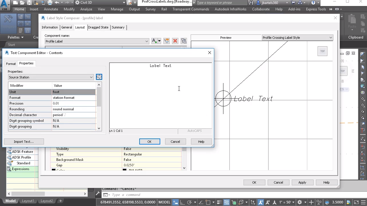
So, I’ll type ELEV period equals. Remember this is just a text editor. I will then come over to the properties menu, and will pull the source elevation. Once again I can adjust its settings, things like units, or precision. I’m gonna keep all the defaults, I’ll just click the arrow to push that over into the editor. I can then come down and click okay and we can see how we’re doing. This looks good.
Looking a little closer we can see the text is centered justified. I’d like to change that, so I’m going to come back to contents and I’ll click the ellipses button. I will then choose the format tab. Here is what we can see the current text style and justification. I’m going to set this to left.
Note that I can also hardcore a font or a color on selected texts, there’s even some additional text accoutrements down here. But right now I’m going to click okay. This looks perfect. I’ll click okay to accept and we’re ready to assign the new label style to this marker. We’ll do that by selecting the marker. I’ll come up to crossing properties, I’ll select this label property and we’ll choose the new profile label. I’ll click okay and okay, I’ll zoom in and we can take a look. I’ll press escape to deselect the marker. This is exactly the annotation I was looking for. Just for a second I’m going to try selecting the label. When I do we get a grip, if I hover over that it says drag label. I can use the script to drag the label out into a leader.
Note that when I drag this away the text gets large. Let’s see why this is. I’m going to press escape to deselect and then I’ll come back and edit the new label style. I’ll do that by right clicking on it and I’ll choose edit. Right here we can see the text tide is .08. Notice that we also have a dragged state tab. These settings control the appearance of the label when it’s dragged away from its original position.
Note that these setting also include a text height and that value is larger, I’m going to set that to .08. And I’ll press enter and click okay and we can be see that change on screen. This label is now exactly the way I want it. I’m going to put it back where it was. I’ll do that by selecting it and then I’ll click this round reset grip. I’ll press escape when finished.
Next, we’ll create a label for the alignment crossing. In this case I’d like the label to run vertically along the line segment and I’d like it to include the crossing object’s name and the station value. To create the new label style I’m going to leverage some of the work that’s already been done. I’ll do that by right clicking on the previous style name and I’ll choose copy. For the name I’m going to call this alignment label.
I will then jump to the general tab, let’s keep the default settings. We’ll go to layout and we’ll zoom in on the preview. I’m going to start by renaming the component and we’ll call this alignment label. I will also reset any offset spec to zero. I would like the label to be visible. I would like it anchored to the marker and I would like it anchored at the middle center. I would like the label rotated 90 degrees and I would like the bottom left of the label to be aligned to the middle center of the marker.
Let’s zoom in and take a look. In this case we have to use our imagination a little bit. We are seeing a sample marker here when in fact we will be labeling a vertical line. Let’s jump to the content setting and I’ll click the ellipses button. I’m already extracting a source object name, I’m going to click after this property and I’ll drag through everything and press delete. I will then add a couple of spaces and will include the station. I’ll type STA period equals, and then will come over and grab the source station property. I’ll click the arrow to push that into the editor. And I’ll click okay. Let’s back up. This looks good. Maybe we’ll adjust the offset a little bit. In this case I’d like to push the label to the left so I’ll assign negative .05 as the X offset.
We’ll do one more thing. I’d like to add a center line symbol in here. So I’ll go back to contents and I’ll click the ellipses button. I will then go to the format tab. Notice there’s a symbol option here. If I open it you can see some of the classic auto kit symbols. In this case I’m going to come down and click other. This brings up the character map. You can see my current font is Roman S. Using the character map I can select any of the other symbols that are a member of this font or any other font for that matter.
Let’s drag down to the bottom of Roman S down here we’ll find a nice center line symbol. I’ll click to select that and then I’ll push the select button and copy to copy that to my clipboard. I will then close the character map, I will click back in the text editor and I’ll press control V to paste the symbol. As a courtesy I’m also getting a character return so I’ll press backspace to remove that. I’ll click okay, this looks perfect. Let’s click okay and we’ll assign the new labels style to the crossing alignment marker.
I’ll select the marker, we’ll go to crossing properties, I’ll choose its label property and then I’ll select alignment label. I’ll click okay and okay. At this point the marker is still selected. Notice I have this diamond grip. If I click this grip, I can drag the label back and forth long the line.
Let’s drag this up and I’ll press escape. If I select the label I’ll get a drag grip, I can use this to pull it out into a leader, once again I’ll deselect. Now this doesn’t look too bad but you know what? When I pull this label into the dragged state I’d rather not have a long line of text. Instead, I’d like to have some word wrap. Let’s look at how we can do that.
I’m going to edit the label style, I’ll right click and choose edit and then on the dragged state tab I’m going to come down and set a maximum text width of one inch. So if this label is pulled into a leader, I’d like a nice one inch wide column of text. Let’s click okay. And you can see the change. This looks good. Same as before I’m gonna put the label back where it was by selecting it and then I’ll click the reset grip. I’ll press escape to deselect.
Finally, I’ll pin the drawing over and will create a custom label style for the crossing feature line. For this example we’ll start by labeling the marker using the standard out of the box label style. I’ll select the marker and we’ll go to properties, I’ll set its label style to standard and I’ll click okay. And okay. Let’s back up. So we can see the label. If I select this we can see a pair of grips, one represents the drag grip and the other one is the label dimension anchor. Keep this one in mind. If I click on this grip, I can use it to drag the label up and down. The goal this time if to build a custom label style that looks and acts just like this one.
That said, I don’t need this label anymore, so I’m going to press delete to remove it. And then I’m going to come over to the standard label that we just used, I’ll right click on that and choose copy. We’ll call this feature label, same as before our general properties we’ll keep the defaults. We’ll go to the layout tab to build our components. I’m going to zoom in. This label style is made up of two components, the crossing text and the line. I’m going to click the delete button to remove both of those and I’m going to start by creating a line component.
So, we’ll open the component menu and I’ll choose line. I will them give this component a name, I’ll call it line segment. We can see that line and its default position down here. I want the line to be visible. I’d like its start point to be anchored to the marker and I’d like it anchored at the middle center. I’d also like to use an endpoint anchor. I’d like the anchor to be relative to the marker and I’d like it at the label dimension grip.
Remember that grip we looked at a couple of seconds ago, by default it’s located about two inches above the marker. From here I can control the line length using percent or a fixed distance, I can change the percentage, I can adjust the offset of the start and endpoint or color and line type of if I want to. For right now this line is perfect. Let’s create another component. I’ll open the component list and I’ll choose text.
We’ll call this component feature label. We can see where it’s sitting by default. I’d like this label to be visible. And this time I don’t want the label to be anchored to the feature, I want it anchored to the line segment. I’d like it anchored at the endpoint.
Let’s zoom in. I’d like the middle left of the label to be attached to the endpoint of the line. Let’s go to contents and I’ll click the ellipses button. I’ll select this generic text and then I’ll come over and we’ll extract the source object name, we’ll make this uppercase and I’ll push that over. I’d like to add this station value, so I’ll type STA period equals. And we’ll include the source station property, I’ll push that over. I will then put my cursor at the end of that text and I’ll press enter, and we’ll add an elevation. And we’ll select the elevation property. And I’ll push that over.
I’d like this text to be left justified, so we’ll go to format and we’ll set this to left. I’ll click okay. One more thing, I’m going to go to the dragged state and we’ll make sure that when it’s dragged out it keeps that same text type of .08. I’ll press enter and okay. Finally, we’ll apply the new label style to the marker. I’ll select a marker, we’ll go to the crossing properties, we’ll go to label property and I’ll choose the new feature label. I’ll click okay and okay. We can see the new label on screen. If I select it I can click the label dimension anchor and pull this up or down.
Let’s zoom in. Likewise, I can use the drag grip to pull the label out and create a leader. At this point we’ve created three custom label styles to help annotate linear profile crossings. Ideally, these styles would be stored in a template to make them available for all future drawings.
After completing this session you have an understanding of the basics of labels style creation for not only profile crossings but every other type of Civil 3D object. Remember that all label styles are created the same way. When you get a chance come back and spend some more time with these tools. With a little creativity, experimentation and practice you’ll be amazed at the number of dynamic label styles you can create using Civil 3D.


