

Quite often a proposed corridor design will require sub assembly parts to transition or change shape as they progress along in alignments. Typically these transitions are controlled using a horizontal, vertical or surface target so long as the sub assembly parts supports it. Not all of them do. In this session, we’ll look at how we can assign transitions to virtually any sub assembly part even if it doesn’t support targeting. We’ll do that by creating a number generator that will calculate the transitions for us. Let’s take a look. As you can see, I have a drawing open in Civil 3D. We’ll talk more about this drawing in just a bit. For right now, I’d like to jump over to sub assembly composer so I can create the number generator. Now, if you’ve never used sub assembly composer before, I have created a series of videos that will help get you started.
I’ll leave a link to those recordings down in the description for this video. Fortunately, the part I’m going to create today can be done in just a couple steps. At the risk of destroying the end of the movie here, just imagine if you could create some profile geometry in Civil 3D instead of elevations. That profile would be used to define numeric values. Those values would then be assigned to sub assembly parts width, length or slope. By doing this, a simple change to the profile geometry would allow that part to transition from one dimension to another. That’s where we’re going to create my number generator. I’m going to start by selecting the packets settings tab and we’ll give this part a name. I’ll call it Number Generator. I can then give this a description. I’ll type calculates values for transitions and I’ll press enter.
Now, since our numbers are going to be coming from a profile, I’ll select the target parameters tab and I’ll create a new parameter. The type will be elevation and I’ll give that parameter a name. We’ll call this Numeric Control Line and then for the display name I’ll type NCL and I’ll press enter. Next, we’ll jump to the input/output parameters tab and then we’ll say that by default when I add this part to an assembly, it will be placed on the right side. I will then create a parameter. It will be an output parameter. This output parameter holds the dimensional values that can be passed to other sub assembly parts. For this example, I’m just going to name it Output Parameter and I’ll press enter. Next, I simply need to assign this numeric value to the output parameter. If I come over to the toolbox, I can drag and drop, set output parameter into the flow chart.
The output parameter I’d like to set is the one I just created. I can then enter a VB expression. Now there’s no magic here. If I come up to the help documentation and choose entering or calculating property data, API functions, elevation target class, we can see the code that I’m going to use right here. Basically it’s the name of the elevation target dot elevation. Let’s close this. For my expression I’ll type numeric control line dot elevation. This expression ensures the numeric value of the target can be passed to other sub assemblies as an output parameter and that’s it. At this point, I can come up and choose file, save as, I’m going to save this PKT file in a directory on my desktop. You can save yours wherever you like. I’m going to call this Number Generator. I’ll click save and we can return to Civil 3D.
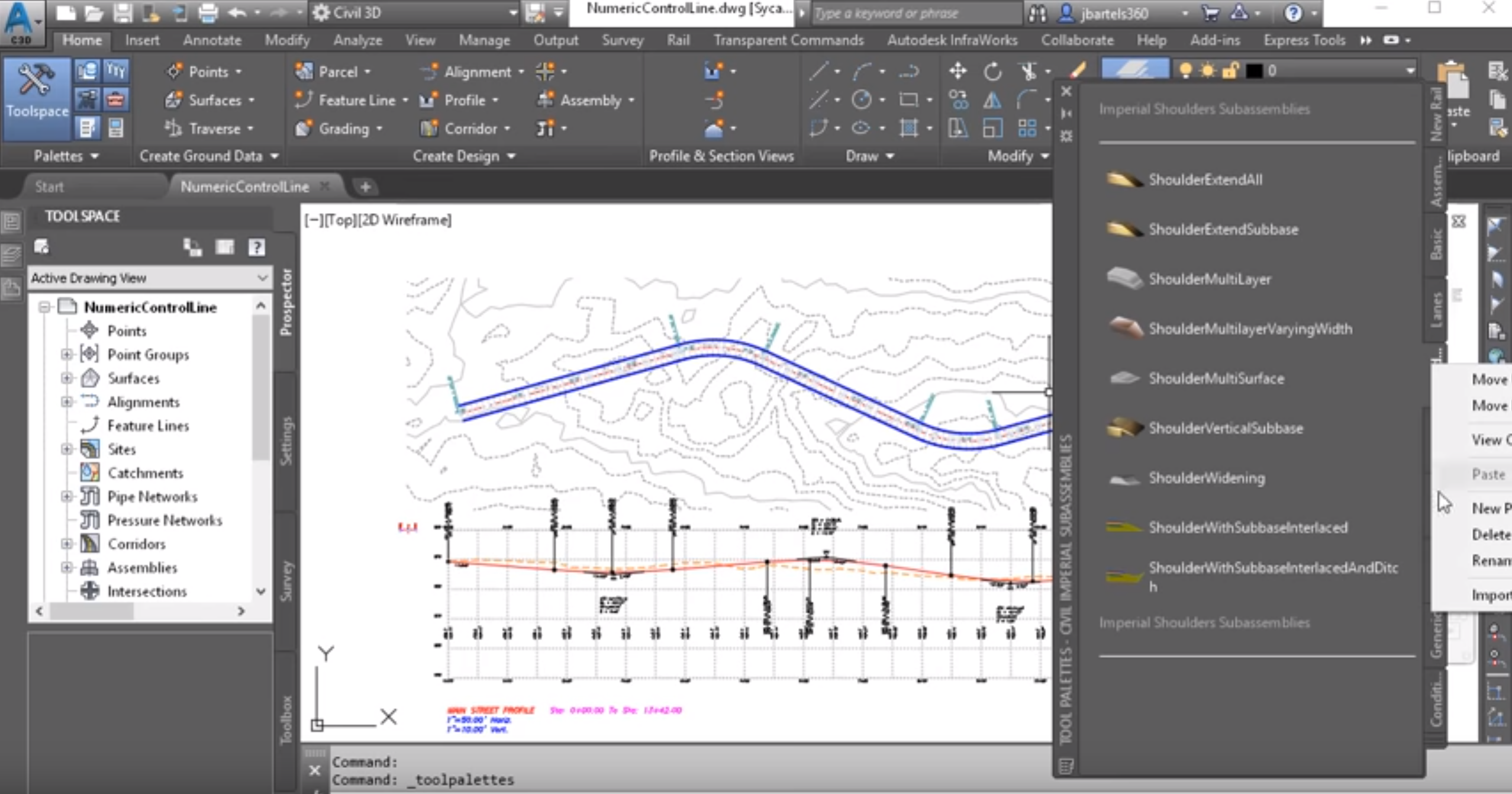
Let’s do one more thing. We’ll load that new tool into the interface. I’m going to bring up the tool pallet. From here, we’ll create a new pallet. I’ll right click on one of these tabs and I’ll choose new pallet. I’ll call this My Custom. Once the pallet’s created, I’ll right click on it. Down at the bottom we’ll find import sub-assemblies. I can then navigate to the directory where I created that PKT file. I’ll select it and click open and okay. Now that the part is available for use, we’ll take a quick tour of the drawing. As you can see, I have some civil components in this file. If I hover, this is an existing ground surface called EG. I also have a proposed roadway center line alignment called Main Street. If we pan down, we can see a profile has been created for that alignment, I have extracted a surface profile for the existing ground.
I have also created a finished grade profile for that alignments. If we pan the drawing over, we’ll see the assembly that was created. This is called Main Street. This defines the typical section for the roadway and I’m just using some generic parts here, basic lane and urban curb gutter general. This assembly was used to build the corridor that we see here. Let’s pan this back. Now let’s say for this example, I would like to transition the width of the flange of this curb. Just for a second, I’m going to come over to the curbs tab. Here’s the part right here. I’m going to right click on that and I’ll choose help. I do this to bring up the help documentation for this part. In the documentation, we can see that a dimension drives that flange width. It’s dimension B. I also bring this up to show you that if we drag this down and look at target parameters, we can see that this object does not support any targets.
Let’s close the documentation. That said, if I select this part and come over to the properties pallet, I can come down to dimension be, currently that’s 16 inches. Let’s set it to 12 inches or one foot. You can see the change on screen. Let me set this to 18 inches. Once again, you can see the change. I’ll press escape. Now that we’ve seen how the dimensional values drive the shape of a part, let’s use our new tool to assign those dimensions. I’m going to select the part and then I’ll come down and choose insert. I’d like to insert it before this lane. Let’s zoom out and we’ll pan that over a little bit and I’ll press escape. If I hover over the new parts, you can see it displays as a pair of rings. I’m going to select it and I’ll go to the properties pallet. Right here I can give my number generator a name, which is great because I can have more than one of these if I want to drive multiple dimensions.
I’m going to call this one Curb Gutter Width. I will then come down to default loop offset. This is the distance that those rings are apart on screen. Let’s set this to 0.5 and I’ll press enter. I will then do a quick re-gen and you could see the change. Now, if I wanted, I could set that measurement to zero when you wouldn’t even know the part was there. That said, if I decide to use several number generators, they may be a little difficult to select. If I did choose to do that, I could select the assembly and go to assembly here on the construction tab. I can always select and edit my parts here. Let’s close this and I’ll close the tool pallet as well.
Let’s do one more thing. I’m going to select my part. We’ll go back to the properties pallet and I’m going to change its default value to one or one foot. I do that because I’m going to assign this flange measurement using the number generator and zero won’t represent a valid dimension. To assign the measurements, I’ll select the assembly and I’ll go to assembly properties. We’ll go to the construction tab and I’ll select the urban curb gutter general on the right side. I will then pull down to find that dimension B. From here, I’ll select to use a parameter reference and from the menu I’ll point to the output parameter coming from my custom part. I’ll click okay and you could see how that object changed. Now if you are new to assigning output parameters, I’ve created a recording that explains that process in more detail. I’ll leave a link to that recording in the description for this video.
I’m going to press escape to deselect the assembly. At this point, the flange dimension is looking at my custom part for its value. Let’s take the concept one step further by linking a profile to the custom part to help us transition between multiple values. Let’s zoom out and pan the drawing over and I’ll select the existing profile. We’ll choose profile view properties and we can see the height is currently set automatic. I’m going to choose user specified. Notice the measurements don’t change, so when I click okay, it still looks the same on screen. I do this because the new profile I create will be significantly lower than the other profiles associated with this alignment and I want to prevent this view from expanding to show that new profile. Instead I’ll create a new profile view by copying this one down. I’ll do that by launching the copy command and I’ll select the profile view and pull it down and drop it here.
I will then select the profile and we’ll go back to profile, view properties and we’ll change the elevation values for this one for the datum or the bottom of the profile, I’ll choose negative 20 and then for the height, I’ll choose 10. I’ll press enter and then I’ll press escape a couple of times to de-select. So, this profile is still associated with the alignments. In fact, it’s the same profile information. I’m just viewing it at a much lower elevation. Now let’s create some profiles geometry that defines the width of our curb flange. I’ll do that by selecting the profile view. I’ll choose profile creation tools. I’ll give the profile and name. I’ll call this Curb Gutter Dimension Line and I’ll click OK. I will then click to draw the profile and I know I want this to run the full length. So, for right now let’s just choose the end points here and then we’ll come over and grab the end point of the other side.
I’ll press enter when finished. I can then bring up the tabular editor and we can assign the flange width for the entire length of the alignment. We’ll say that it starts at one foot wide and it ends at one foot. I’ll close the tabular editor and the toolbar. Let’s do one more thing. I will select my corridor. Now we’ll choose edit targets and I’ll click inside my region. Here’s my custom sub assembly part. I can now point that to the profile that we just made. I’ll click add and okay and okay. Now we don’t see a change just yet because the flange width remains at one foot wide. Now I can come down and edit the geometry of this profile to drive the dimensions of that flange. I’m going to select the profile and then I’ll choose geometry editor. I will then click to add a PVI.
Let’s add one. I’m going to come over and use a transparent command, profile station and elevation. I will then select the profile view and we’ll add a PVI at station 100. We’ll set this to one foot, maybe station 200. We’ll set this to something obviously different, two and a half feet, maybe. Station 300 we’ll assign two and a half feet. Station 400 we’ll set that to maybe a half a foot wider. Let’s drag this down. Station 500 we’ll transition that back to one foot. I’ll press enter a couple of times when finished. I’ll close the toolbar and I have a nice easy to edit graphical representation of the transitions that connect my desire to dimensions. Finally, we’ll zoom out and go back to the corridor. I’ll select this and I’ll choose rebuild. You can see the change. I’ll press escape. Let’s select the corridor down here before station 100. I’ll choose section editor and then as I stepped through these sections, we’ll see that flange with change from one foot out to two and a half.
It will maintain that measurement for 100 feet and then it will transition back to a half a foot and then immediately transition back out to one foot. When I’m finished reviewing the corridor, I’ll click the green check to close the section editor and then I’ll double click the mouse wheel to do a zoom extents. It’s important to note that in this example, I’m using the numeric control line to drive the width of a sub assembly part. That said, this profile is simply a graphical way of calculating numbers, so this technique can be applied to virtually any dimension or slope. By leveraging multiple control lines, you can unlock a whole new world of transitional opportunities in your next court or design.


